
Partner projects / Selected engineering
Engineering in focus.
A closer look at seven projects across smart hospitality, wireless control, wearable sensing, connected tracking, inspection software and drone electronics.
Smart hospitality
PickPlace
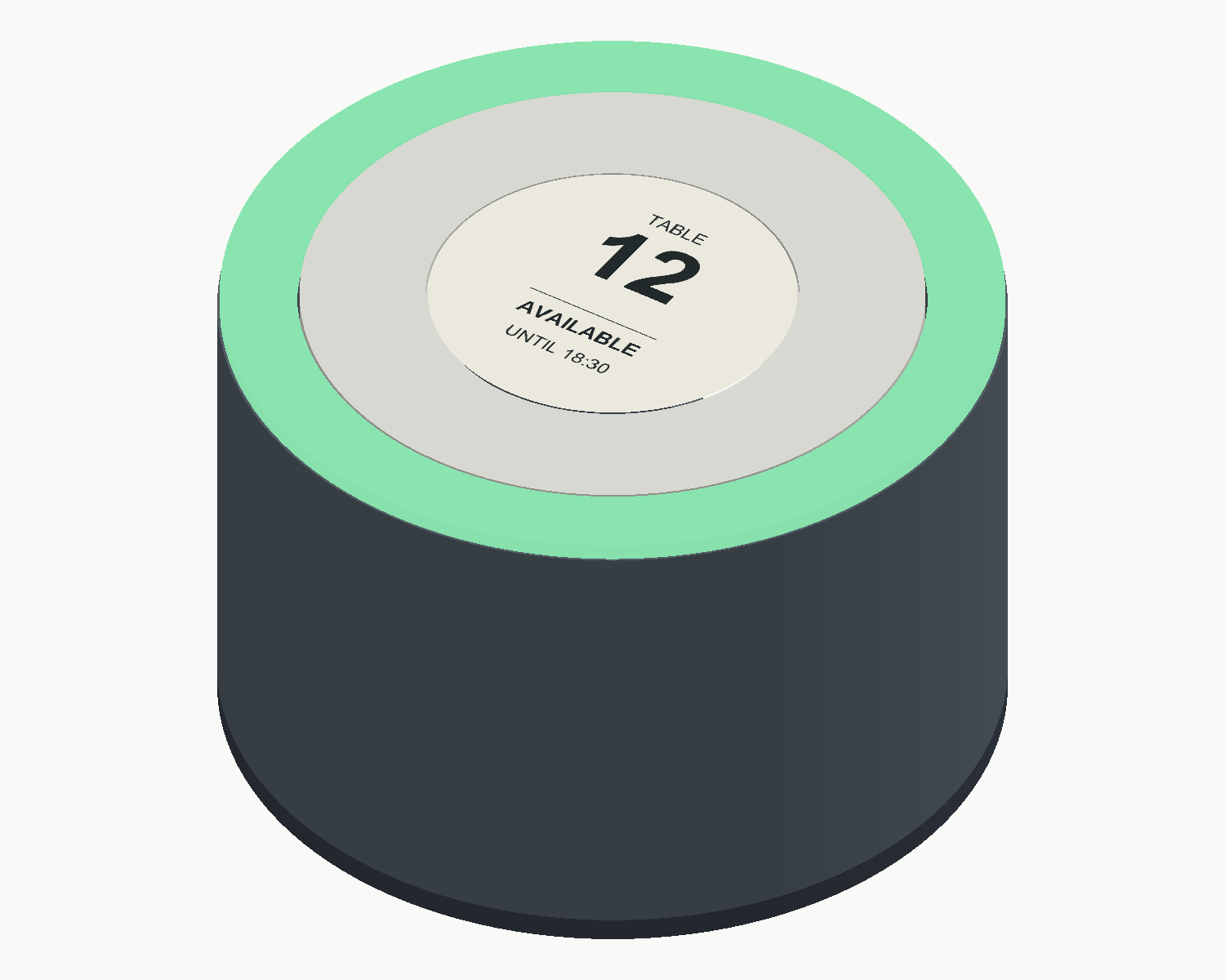
Table status,
clear at a glance.
A connected table-status and reservation concept for hospitality. PickPlace brings together a compact e-paper table device, a visible RGB status ring, rechargeable electronics and a USB radio gateway.
- System concept
- Table devices & USB gateway
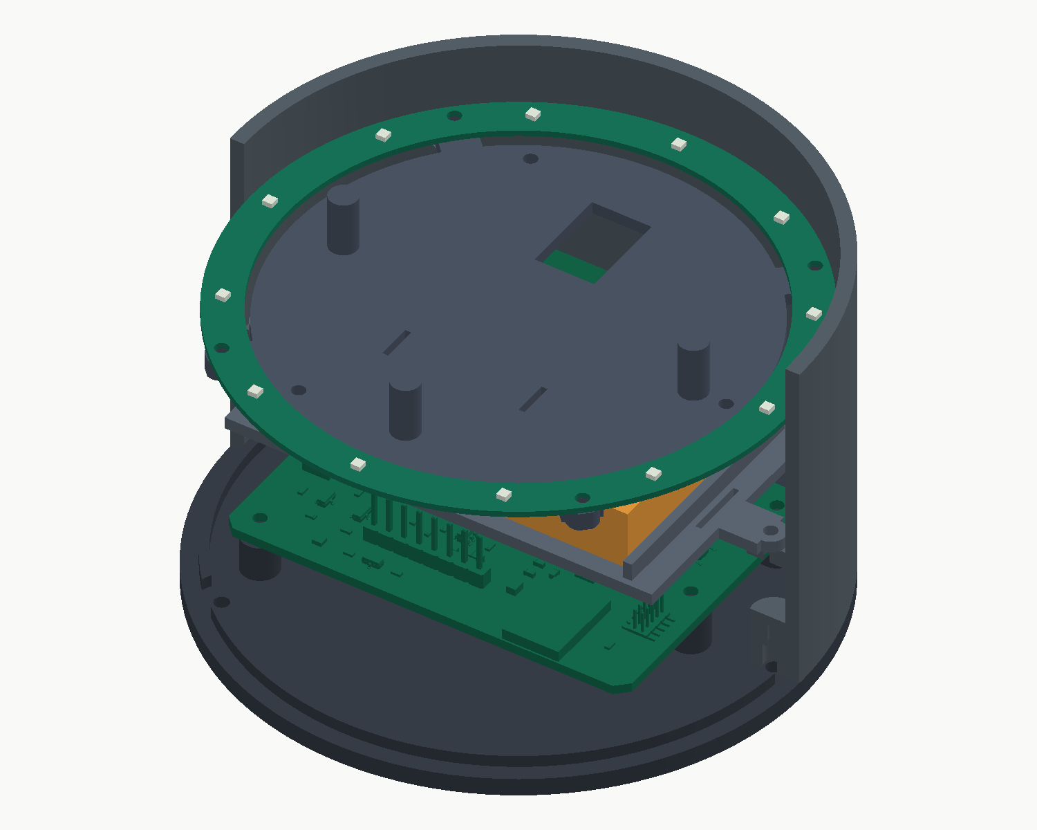
- Round enclosure
- Ø96 × 62 mm CAD design
- Engineering scope
- PCB design & mechanical CAD
- Project stage
- Design prototype
Round-display and light-ring integration are in development. Firmware and reservation software are planned.
Explore PickPlace hardware & system concept
Original engineering views
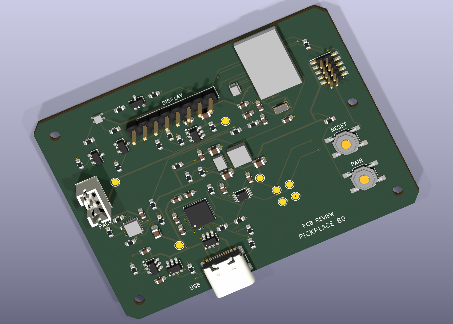
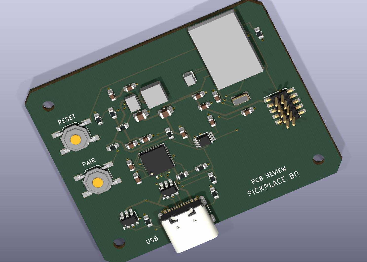
Table-device and gateway PCB renders, plus a cutaway of the round enclosure. Select a view to inspect the original CAD image.
Designed around the table-service workflow
Clear table information
The planned e-paper interface shows the table number, availability and next booking time. Text accompanies the status-light colours, with a QR link for guest requests.
Connected fleet
The architecture targets up to 50 table devices through a PC-connected USB radio gateway. USB-C is planned for charging, pairing and table-number setup; fleet capacity needs physical validation.
Staff-managed reservations
The proposed workflow sends guest requests to staff for approval. Device firmware, PC management and the reservation service are future development stages.
The current package contains table-device and gateway PCB designs and a round enclosure CAD model. The B1 lighting ring and round display still require electrical integration. The renders illustrate the design; physical operation, radio performance and battery runtime remain to be validated.
Wireless relay control
Wireless Controlled Switch
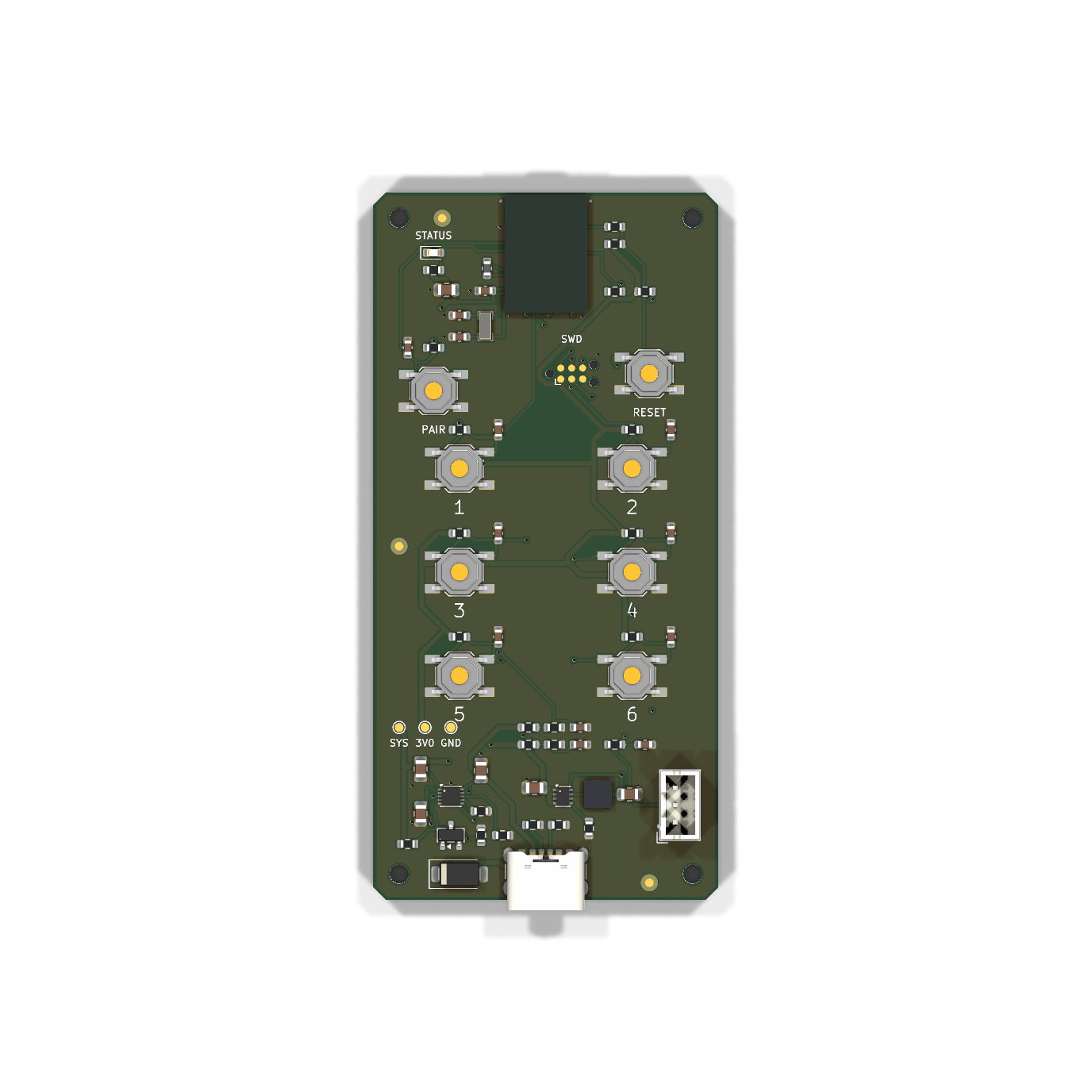
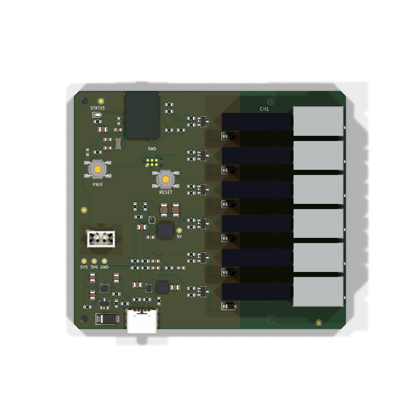
Six buttons.
Wireless control.
A hardware design for Bluetooth Low Energy control: a six-button handheld transmitter and a separate six-channel relay receiver, both built around Nordic nRF54L15 radio modules.
- Remote board
- 40 × 82 mm · 6 buttons
- Receiver board
- 80 × 70 mm · 6 relays
- Radio platform
- nRF54L15 / Raytac AN54LQ-15
- Project stage
- Engineering pilot design
PCB and schematic designs are complete. Firmware development and physical testing remain to be completed.
Explore Wireless Controlled Switch hardware & control concept
A dedicated remote and a separate switching unit
The MastSlave project contains two independent KiCad designs. The remote provides the user controls; the receiver provides six separate normally-open relay contact channels for externally powered loads.
Handheld controls
Six numbered momentary buttons, dedicated pairing and reset controls, a status LED and programming access on a compact four-layer board.
Relay receiver
Six electromechanical relays with individual coil drivers, flyback protection and separate output terminals. The PCB separates relay contacts from the logic circuitry.
Wireless control plan
The firmware contract specifies bonded BLE communication, complete channel-state commands and outputs switching off after a lost connection or reset. These behaviours require implementation and hardware testing.
Power design
Both boards include an external protected single-cell battery interface, USB-C power input and charging circuitry. The receiver adds a dedicated supply for its relay coils.
Engineering package
Editable schematics, routed four-layer PCBs, component lists and fabrication and assembly files are available within the project. The images above are original CAD renders.
Next development stage
Firmware implementation, first-article assembly, battery qualification, radio testing and load-specific relay validation are planned before deployment.
Current status: unbuilt engineering pilot. CAD verification does not establish operating range, battery runtime or switching performance.
Wearable sensing
Foot Force
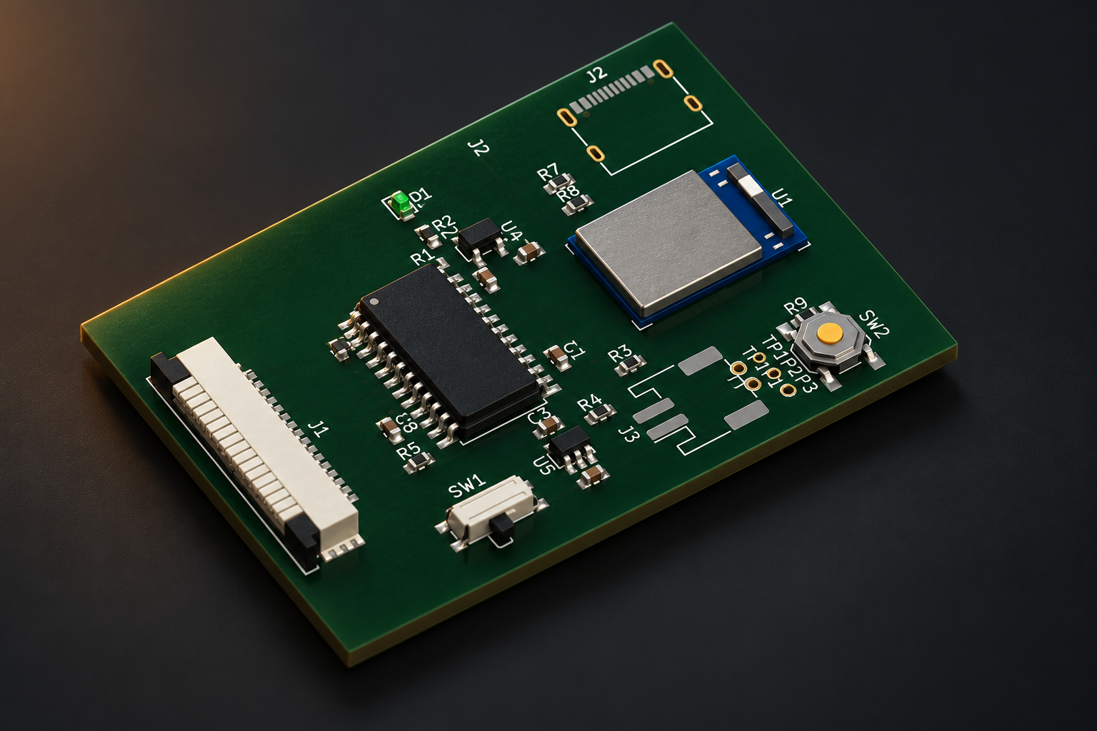
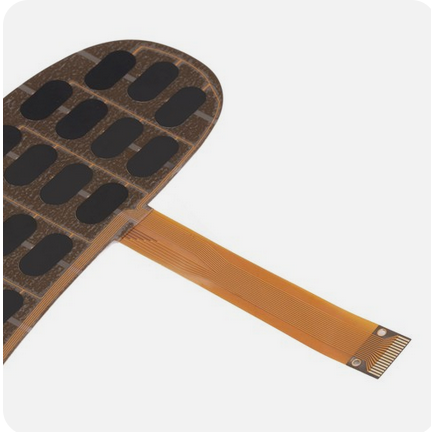
From pressure sensing to wireless insight.
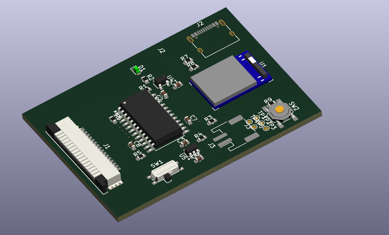
A wearable sensing platform pairing a flexible pressure-sensor array with a compact Bluetooth controller for movement and pressure-distribution analysis.
- Sensor interface
- 16 channels
- Connectivity
- Bluetooth Low Energy
- Hardware
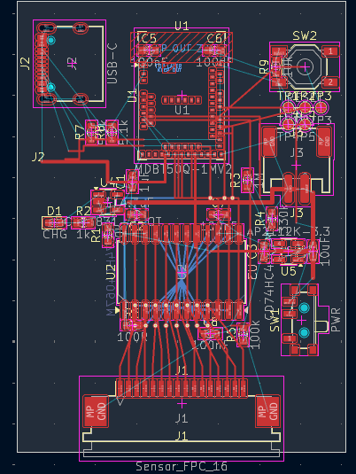
- Sensor array & controller PCB
Project partner MediaTek ↗
Explore Foot Force engineering details & original CAD
Original engineering views
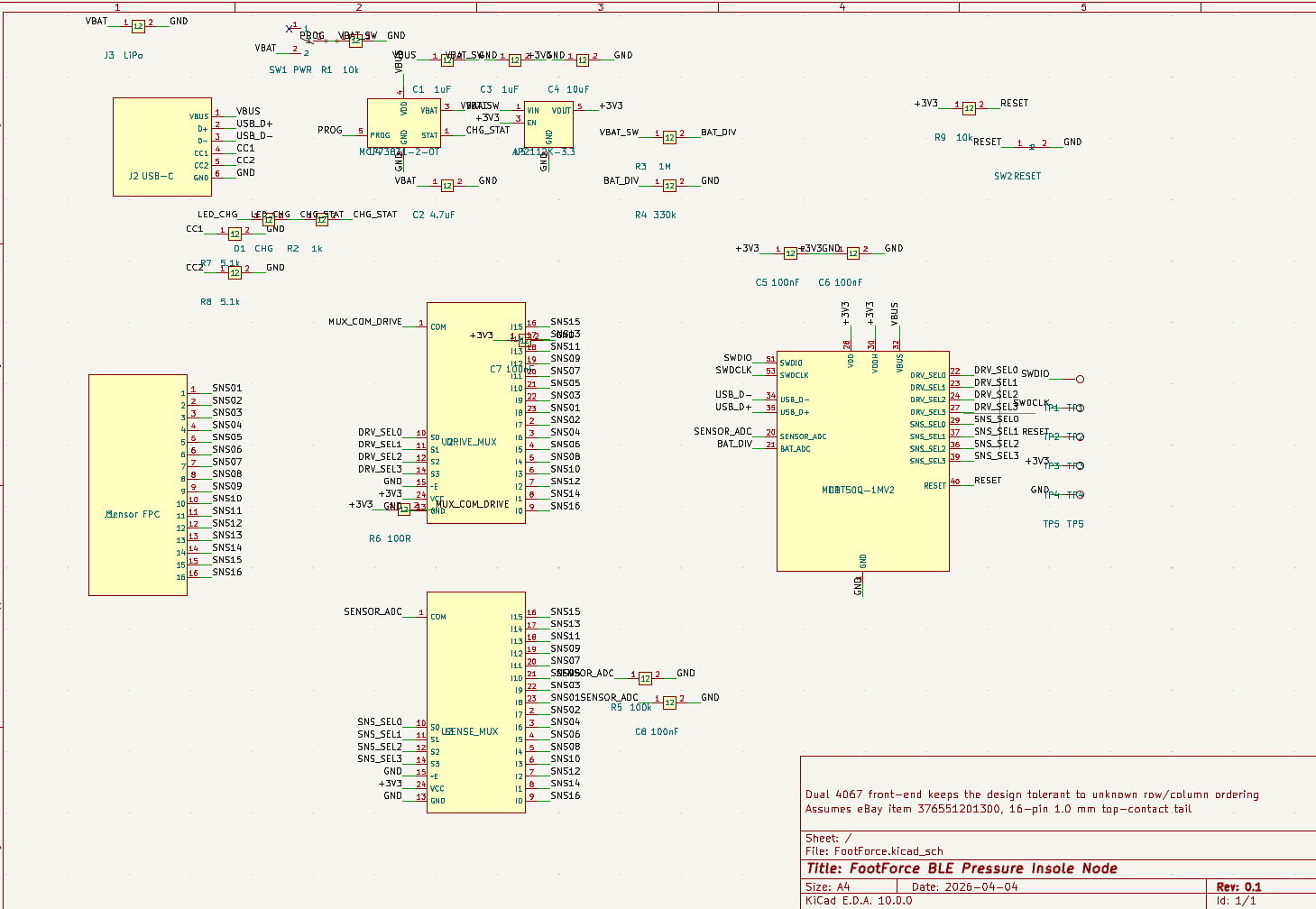
Source CAD and design documents. Select an image to inspect the original at full size.
Technology & project specifications
BLE 5.0 SoC
MDB750Q-1MV2 Bluetooth Low Energy system-on-chip. Ultra-low power wireless streaming of all 16 sensor channels at up to 100 Hz sampling rate.
16-Channel Sensor Array
Flexible insole with 16 precision force-sensitive resistors covering heel, arch, metatarsal, and toe zones. Full plantar pressure mapping in real-time.
Analog Multiplexer
High-speed analog MUX with 74HC4067 scans all 16 sensor channels sequentially. Driven by precision DRV_SEL lines for clean signal acquisition.
USB-C & LiPo
Onboard LiPo charging via USB-C with charge status LED. Battery voltage monitoring for low-power alerts. Full day of clinical use on a single charge.
Smartphone App
Live pressure heatmap visualization on iOS/Android. Record sessions, compare left vs. right foot, track gait symmetry, and export CSV data for analysis.
Ultra-Thin Design
Flexible sensor PCB at just 0.8mm thickness fits inside any shoe. Lightweight FPC cable connects to the ankle-mounted controller unit.
- 16
- Pressure sensors
- 100 Hz
- Sampling rate
- BLE 5.0
- Wireless streaming
- 0.8mm
- Sensor thickness
Use cases
Sports Performance
Analyze running gait, optimize foot strike technique, measure force asymmetry. Used by coaches and sports scientists worldwide.
Medical Rehabilitation
Post-surgery gait recovery tracking, diabetic neuropathy monitoring, orthopedic assessment. Clinical-grade pressure data for healthcare professionals.
Custom Orthotics
Generate precise pressure maps to design perfectly fitted custom insoles and orthotics. Data-driven footwear customization.
Bluetooth key tracker
Air Tag
Small footprint.
Everyday essentials.
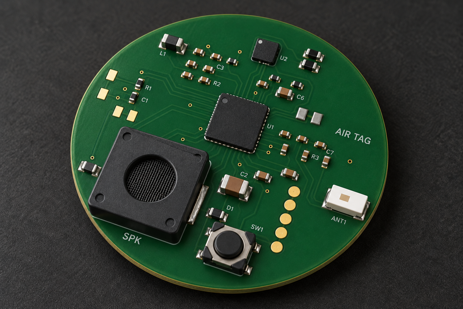
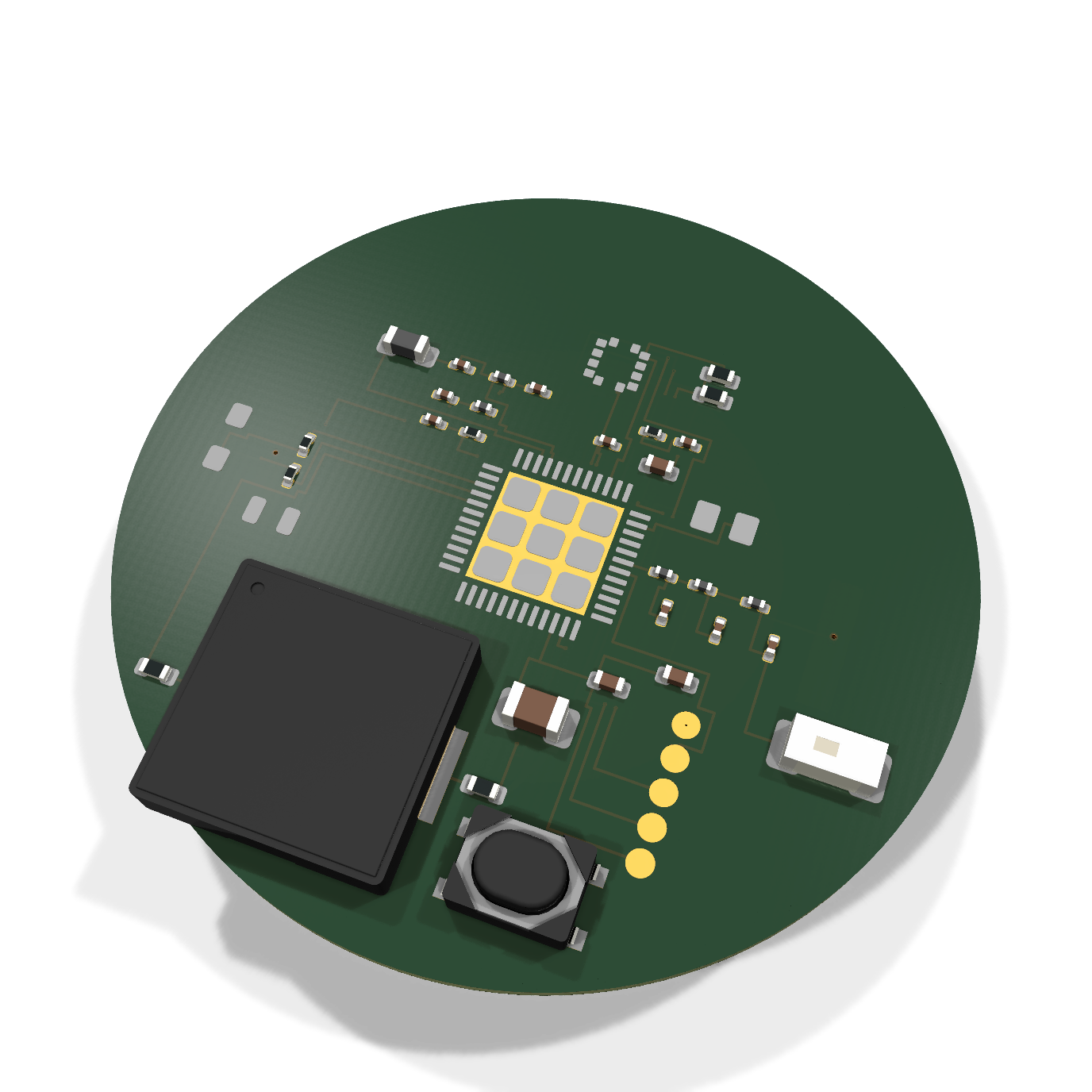
A compact key-tracker hardware design built around Nordic nRF54L15, combining Bluetooth Low Energy, motion sensing, an NFC interface and a compact piezo speaker for audible identification. A replaceable CR2032 powers the circular PCB.
- Board format
- Ø31.9 mm · 4 layers
- Controller
- Nordic nRF54L15
- Speaker
- Compact piezo sounder
- Project stage
- Engineering prototype design
Firmware, enclosure integration and physical validation are future development stages.
Explore Air Tag hardware & design details
PCB presentation & original engineering views
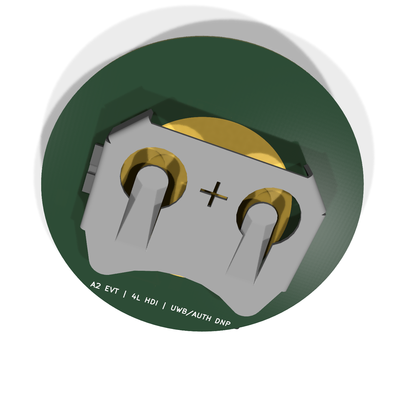
The cover is an AI-assisted concept visualization based on the controller CAD, with illustrative trace geometry, populated components and a compact piezo-speaker package. The original controller and battery-side CAD views remain below and can be opened at full size.
Compact hardware for a personal key tracker
Bluetooth connectivity
Nordic nRF54L15 forms the controller and Bluetooth Low Energy platform for the planned short-range identification and phone-interaction workflow.
Motion sensing
An ADXL367 accelerometer supports the planned movement-detection and wake-up functions, with firmware behaviour to be developed and tested.
Replaceable coin cell
The CR2032 battery interface sits on the reverse of the PCB. Power decoupling and battery monitoring are included in the hardware design.
NFC & piezo speaker
The board includes an NFC inlay interface and a differential piezo-speaker output for audible identification. The cover illustrates a compact speaker package; final sounder selection, antenna tuning and acoustic performance need validation in the enclosure.
Four-layer board
The 31.9 mm circular PCB has a nominal thickness of 0.8 mm. Editable schematics, routed board files and fabrication outputs form the engineering package.
Prototype development
The current work is an engineering design. Firmware implementation, assembled-board testing, RF tuning and enclosure qualification remain future stages.
This is an independent hardware design. The current PCB has no GPS; UWB and authentication interfaces are reserved with components intentionally unpopulated. Find My network operation is outside this hardware baseline.
Connected tracking
GPS Tracker 4G
Compact hardware. Connected assets.
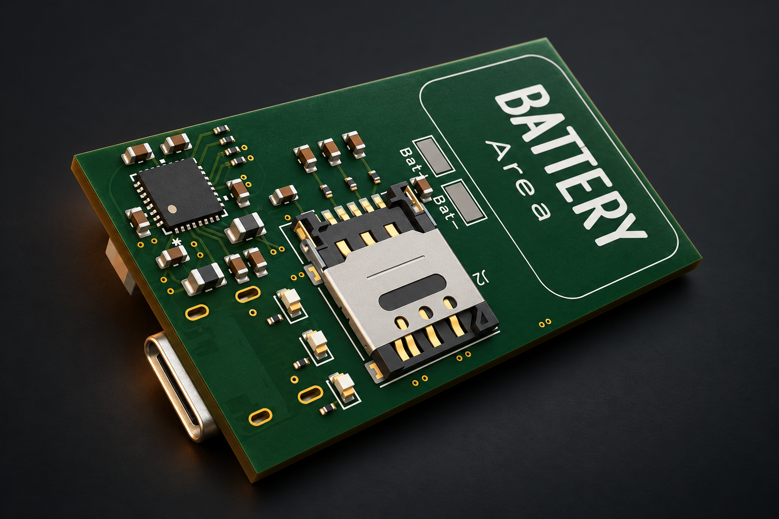
A cellular tracking platform bringing positioning, power management and embedded firmware together on a compact custom PCB.
- Platform
- Nordic nRF9161
- Power management
- nPM1300
- Engineering scope
- PCB design & embedded firmware
Project partner DroneOps ↗
Explore GPS Tracker 4G engineering details & original CAD
Original engineering views
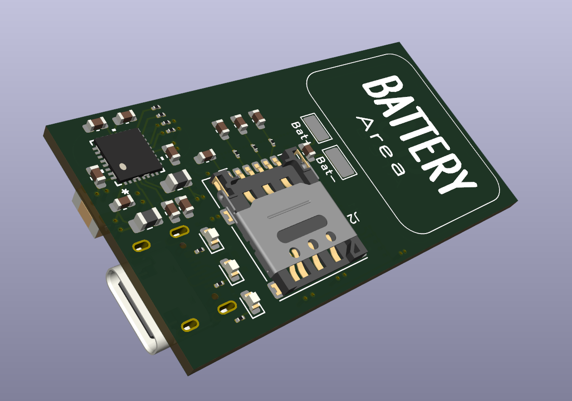
Source CAD and design documents. Select an image to inspect the original at full size.
Technology & project specifications
nRF9161 SiP
Nordic’s latest cellular IoT System-in-Package with integrated LTE-M/NB-IoT modem, GNSS receiver, and Arm Cortex-M33 processor. Single-chip solution eliminating external components for minimal BOM cost and PCB footprint.
nPM1300 PMIC
Nordic’s ultra-efficient Power Management IC with integrated battery charger, dual LDO regulators, and buck converter. Intelligent power path management ensures maximum battery life with seamless charging.
Multi-GNSS
Integrated GNSS receiver supporting GPS, GLONASS, Galileo, and BeiDou constellations. Sub-meter positioning accuracy with assisted GNSS (A-GNSS) and predicted GNSS (P-GPS) for ultra-fast cold start times under 3 seconds.
Deep Sleep Mode
System-level deep sleep current consumption as low as 2.5 µA. Wake-on-event triggers via accelerometer or RTC timer. Enables deployment periods of 5+ years on a single battery depending on reporting interval.
Flash Memory
Ultra-low power 1.8V NOR Flash memory for offline data logging and FOTA (Firmware Over-The-Air) updates. Minimal standby current of <1 µA ensures negligible impact on battery life even during extended storage periods.
1.8V System Rail
Entire system designed around a 1.8V power rail — the lowest operating voltage for maximum energy efficiency. Every component selected for minimal quiescent current. Total system standby under 5 µA.
- < 5 µA
- System deep sleep current
- < 3 sec
- GNSS TTFF with A-GNSS
- 1.8V
- System rail
- 5+ years
- Battery-life specification
PCB design: 6-layer impedance-controlled layout with dedicated ground planes and RF antenna matching.
Firmware: Zephyr RTOS and the Nordic nRF Connect SDK, including power management, FOTA and cloud connectivity.
Electronic inspection app
VidVal
Inspect electronics.
See the differences.
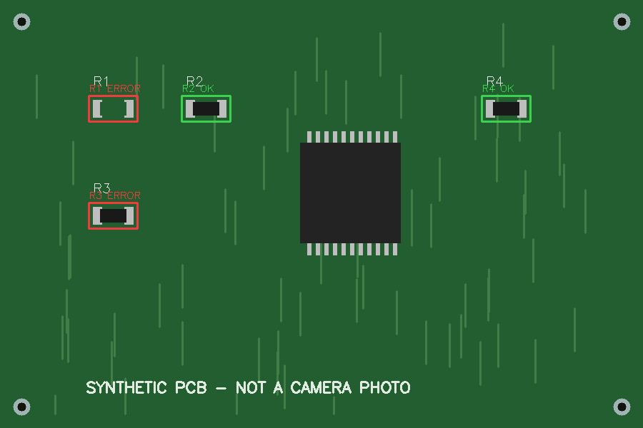
A Windows desktop app for visual PCB inspection. VidVal compares camera captures or saved board photos with known-good references, highlights differences in configured component regions, and helps operators review the results.
- Platform
- Windows desktop
- Image input
- USB camera & saved photos
- Inspection records
- Annotated images, JSON & CSV
- Project stage
- Working prototype
Visual checks cover the configured regions. Recipes need validation with the intended camera, lighting and physical boards before production use.
Explore VidVal inspection features & workflow
From reference photo to inspection record
Set up a recipe with at least three known-good references, define the component areas to check, then capture or load a board image. Review any flagged differences before saving the inspection record.
Component & DNP checks
Define regions for populated components and do-not-populate locations. Set a difference threshold for each check and flag appearance changes against the closest matching reference.
Camera & photo workflow
Capture and inspect with F5, then move to the next board with F6. A stable-frame check helps reject unsettled captures; saved photos can also be inspected.
Detailed comparisons
Compare the selected reference, aligned board crop and difference heatmap. Zoom and pan help review small component regions at their original image resolution.
PCB version recognition
Use visually distinctive regions to compare saved version recipes. Unknown or ambiguous matches are reported for review.
Image-quality checks
Configurable focus and brightness checks help reject unsuitable captures. Independent good and faulty photos can be used to evaluate a recipe.
Traceable inspection records
Save original, aligned and annotated images with JSON and CSV reports. Records include the entered board ID, operator, checked regions, thresholds and recipe fingerprint.
Built with Python and OpenCV; image processing runs locally. The example above uses synthetic demo data. Appearance comparison does not verify component values or electrical function.
Drone electronics
8Bit-Drone v1.0
Compact electronics.
A complete drone concept.
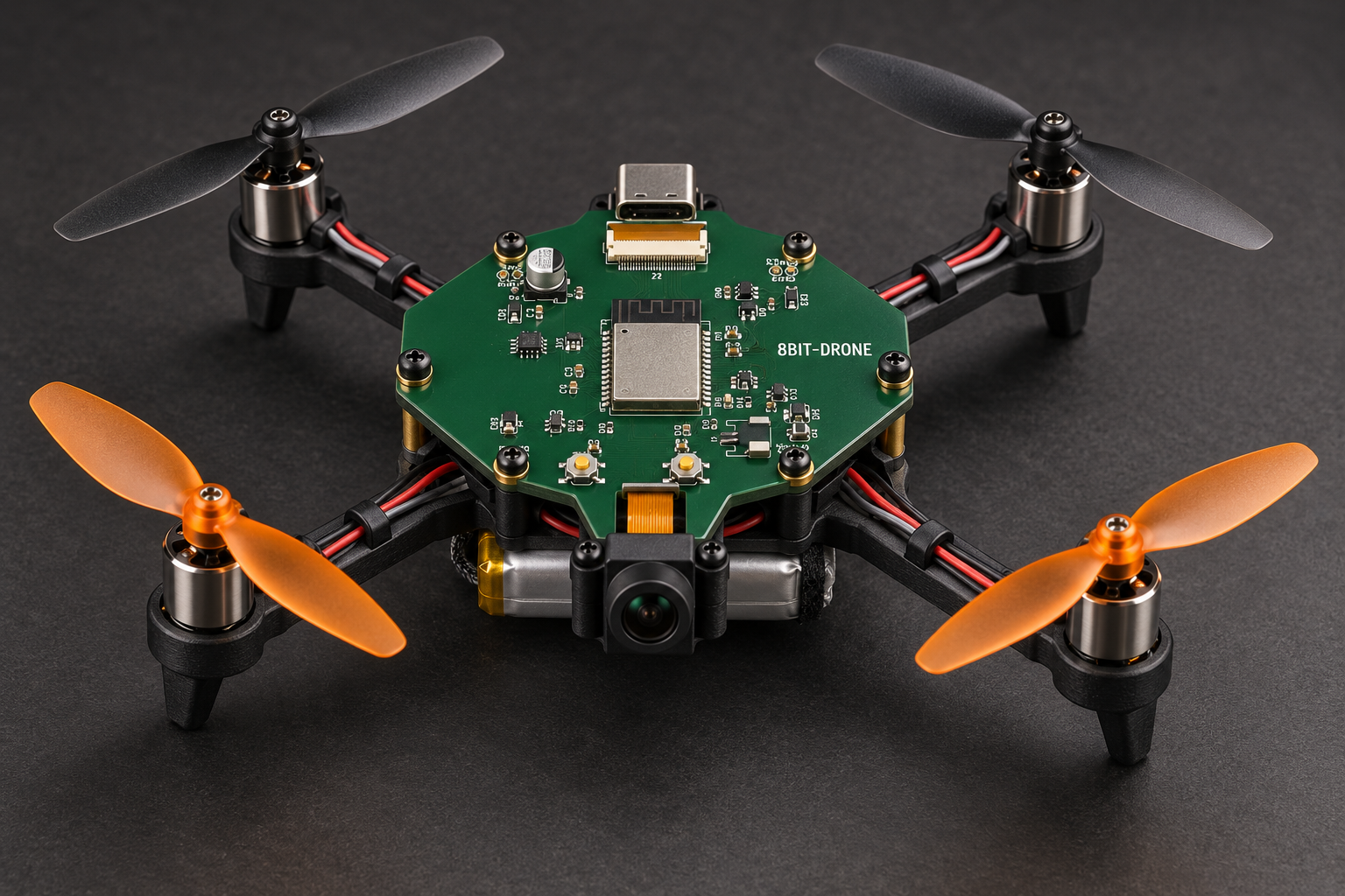
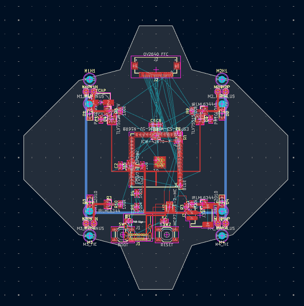
An ESP32-S3 controller design for a compact camera-equipped quadcopter, bringing wireless connectivity, motion sensing and four-motor control into a proposed lightweight assembly.
- Processor platform
- ESP32-S3
- Camera interface
- OV2640
- Motion sensor
- ICM-42670-P
- Cover image
- Assembly concept
Project partner MediaTek ↗
Explore 8Bit-Drone v1.0 engineering details & original CAD
From controller CAD to assembly concept
The cover is an AI-assisted visualization of a proposed drone assembly. Frame, motors, camera and battery placement illustrate the integration concept. Original PCB, schematic and layout views are preserved below; select an image to inspect it at full size.
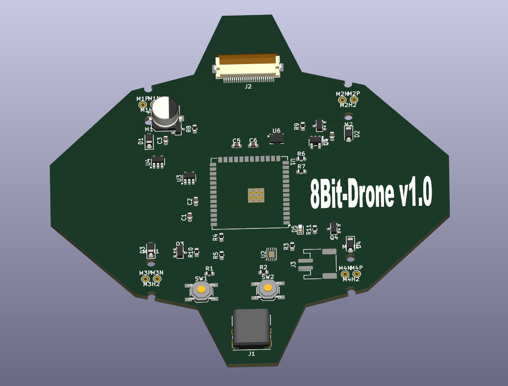
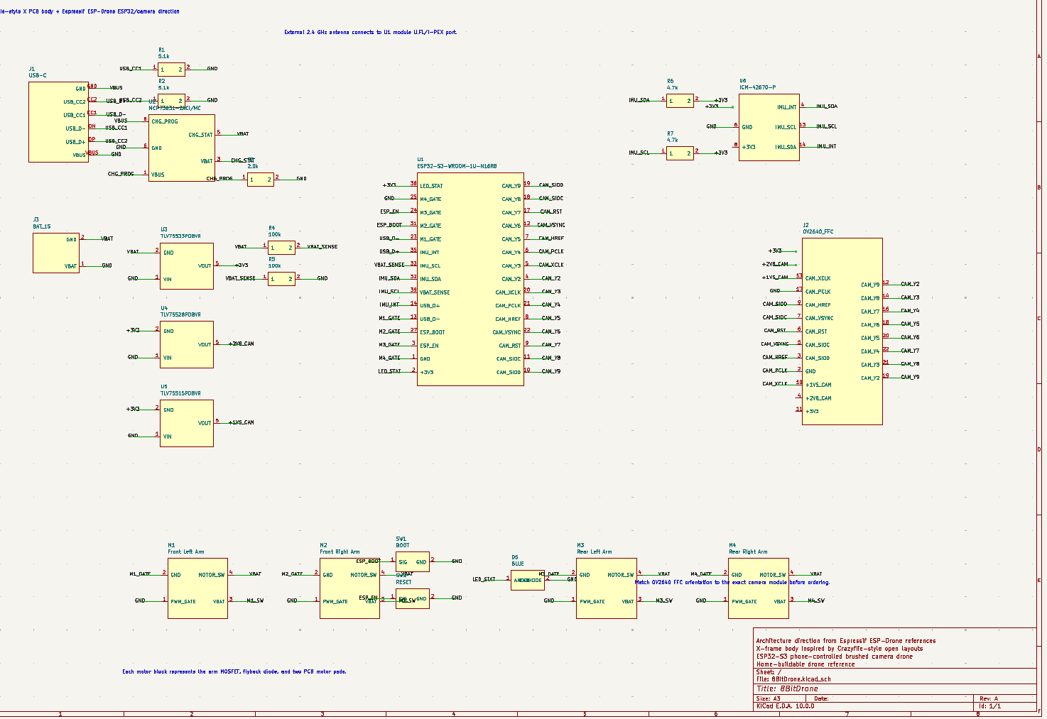
Open-source architecture reference: Espressif ESP-Drone ↗ · GPL-3.0 licence ↗. Consulted for general microdrone construction; the cover is an original concept visualization.
Technology & project specifications
ESP32-S3
Dual-core Xtensa LX7 @ 240 MHz with 16MB Flash & 8MB PSRAM. WiFi 802.11 b/g/n for direct smartphone pairing. BLE 5.0 for telemetry.
OV2640 FPV Camera
2MP onboard camera with real-time MJPEG streaming to your phone. Up to 30fps video feed over WiFi for immersive first-person flight.
ICM-42670-P IMU
TDK InvenSense 6-axis motion sensor with 3-axis gyroscope & accelerometer. Enables stable flight control, auto-leveling, and crash detection.
4-Channel H-Bridge
IRLML6344 MOSFET-based motor drivers with independent PWM control for each rotor. Sub-millisecond response time for agile maneuvers.
USB-C & LiPo
MCP73831 charge management with single-cell LiPo. Multi-rail power design (3.3V, 4.2V, 1.8V) via TLV755 ultra-low-noise LDOs.
CAN Bus
Integrated CAN interface for external sensor expansion, payload modules, or multi-drone fleet communication at distances up to 50m.
- 50m+
- WiFi control range
- 30 fps
- FPV video stream
- 240 MHz
- Dual-core processor
- ~8 min
- Flight-time specification
Hardware covers show CAD renders and presentation visualizations. The Air Tag and drone covers illustrate proposed assemblies. VidVal shows an inspection result using synthetic demo data. Expand each project for original engineering views or software workflow details.
Let’s build your next project.
Custom electronics, embedded firmware, inspection software and connected systems.
8-Bit Lab Engineering · Hardware / Firmware / Software / IoT